Sat 08/29/20 08:58:14 pm
Categories:
Electronics
I am building a Coffee Can Radar. Here is the modulator.
I have been working on this project for a few months. Most of the initial work was ordering parts and learning how the parts work. The project is from a course that was first offered nine years ago and some of the parts are no longer manufactured. I was able to find new or used versions of everything except the voltage controlled oscillator (VCO) component. (I did find a few used versions of the required VCO but they all cost about US$ 300. This was well outside the project budget, and unreasonable for a part that originally cost about US$ 40.) After reviewing specifications of the original VCO and currently available parts I had a few options: get a different model VCO component for US$ 50-150, or assemble one myself with a surface mount VCO chip, circuit board, and connector for about US$ 50. With the latter option I could get a VCO chip with specifications very close to the original requirement. If the assembly was successful I would have a component equivalent to the one from the original design. However, the VCO chips are only available in surface mount QFN packages. I am just starting to learn to solder and I do want to try surface mount soldering. However, for this project I decided that learning lead-free SMD QFN soldering technique (or hot plate or oven methods) would add too much complication, risk, and delay. I decided to order a low cost VCO component and hope I can figure out how to modify other parts of the design to make it work.
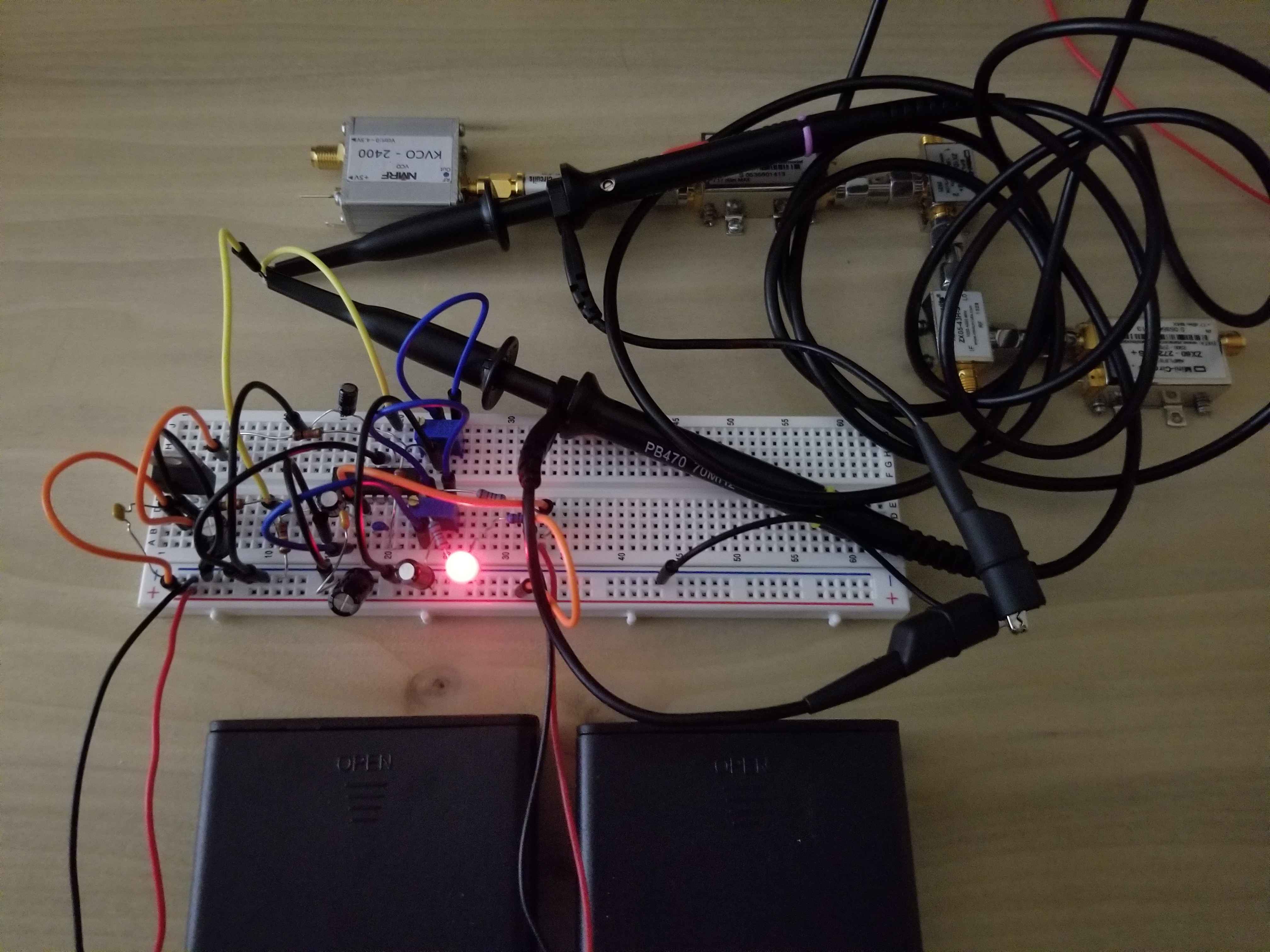
So far I have assembled the RF components, the power supply circuit, and the modulator circuit:
The modulator circuit uses the XR2206 function generator IC, the same one used in the signal generator kit I built.
The modulator drives the VCO to produce a Frequency Modulated Continuous Wave. I successfully tuned the circuit to produce the required 20ms up ramp output (yellow) and synchronization output (purple):
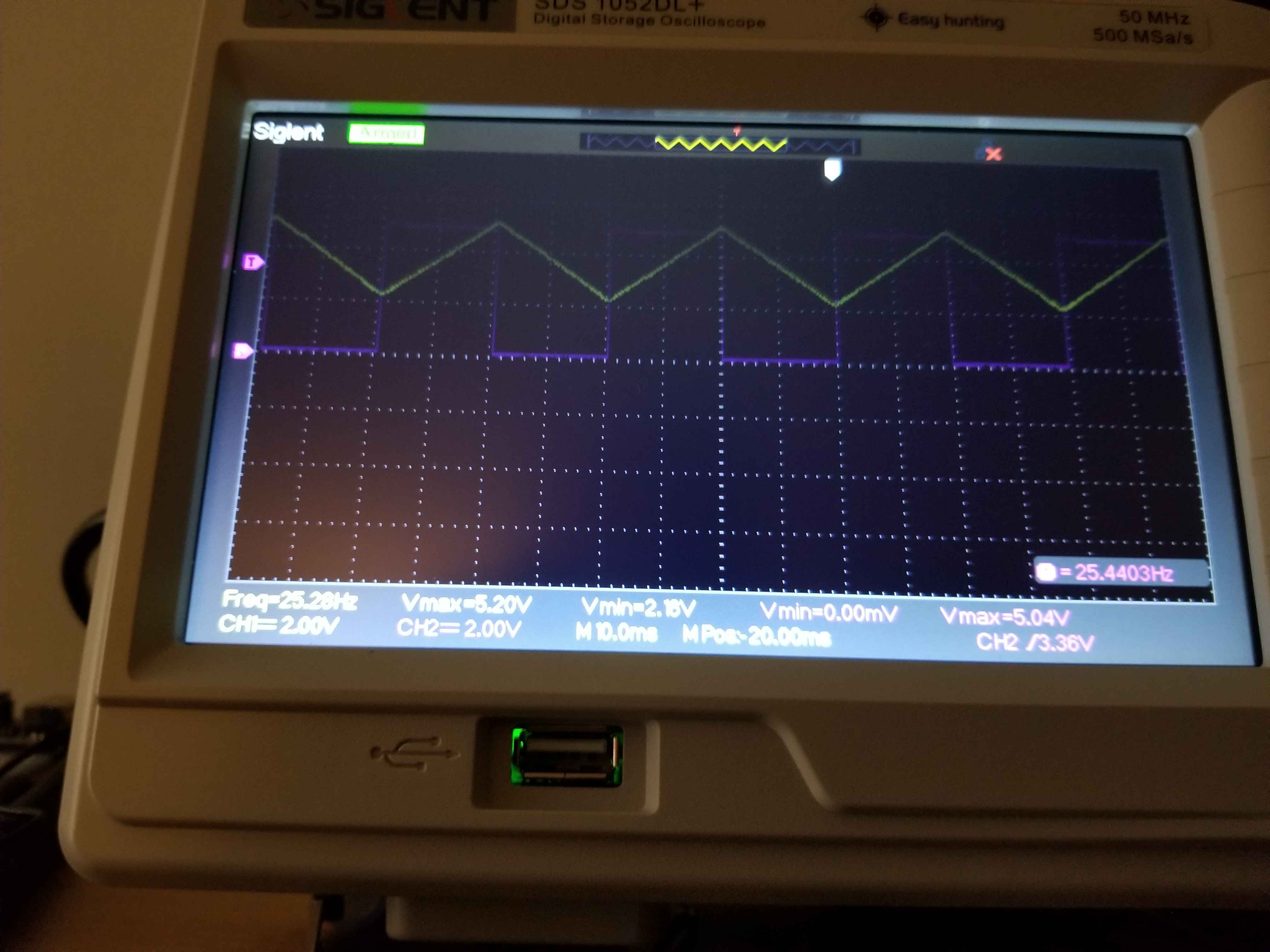
The ramp voltage range required for the original VCO is 2V to 3.2V. I was not able to get this range (I had 2.2V to 5.2V when I took the above picture) but I didn’t spend much time on it. According do the documentation I need a range of 1V to 2.2V for the VCO I am using. I have a plan to modify the modulator circuit to get this range and will test it when I connect and test the RF components.
subscribe via RSS