Sun 06/28/20 03:17:29 pm
Categories:
Electronics
This is my first circuit using a transistor as a switch. I used this circuit to measure the frequency of the square wave test signal from my multimeter.
Previously I wrote about testing my ocsilloscope with the square wave test signal from my multimeter. The multimeter documentation said the test signal was 50 Hz, but the oscilloscope measured the frequency at 52.3 Hz. At the time I did not know if the oscilloscope was off or the multimeter was off.
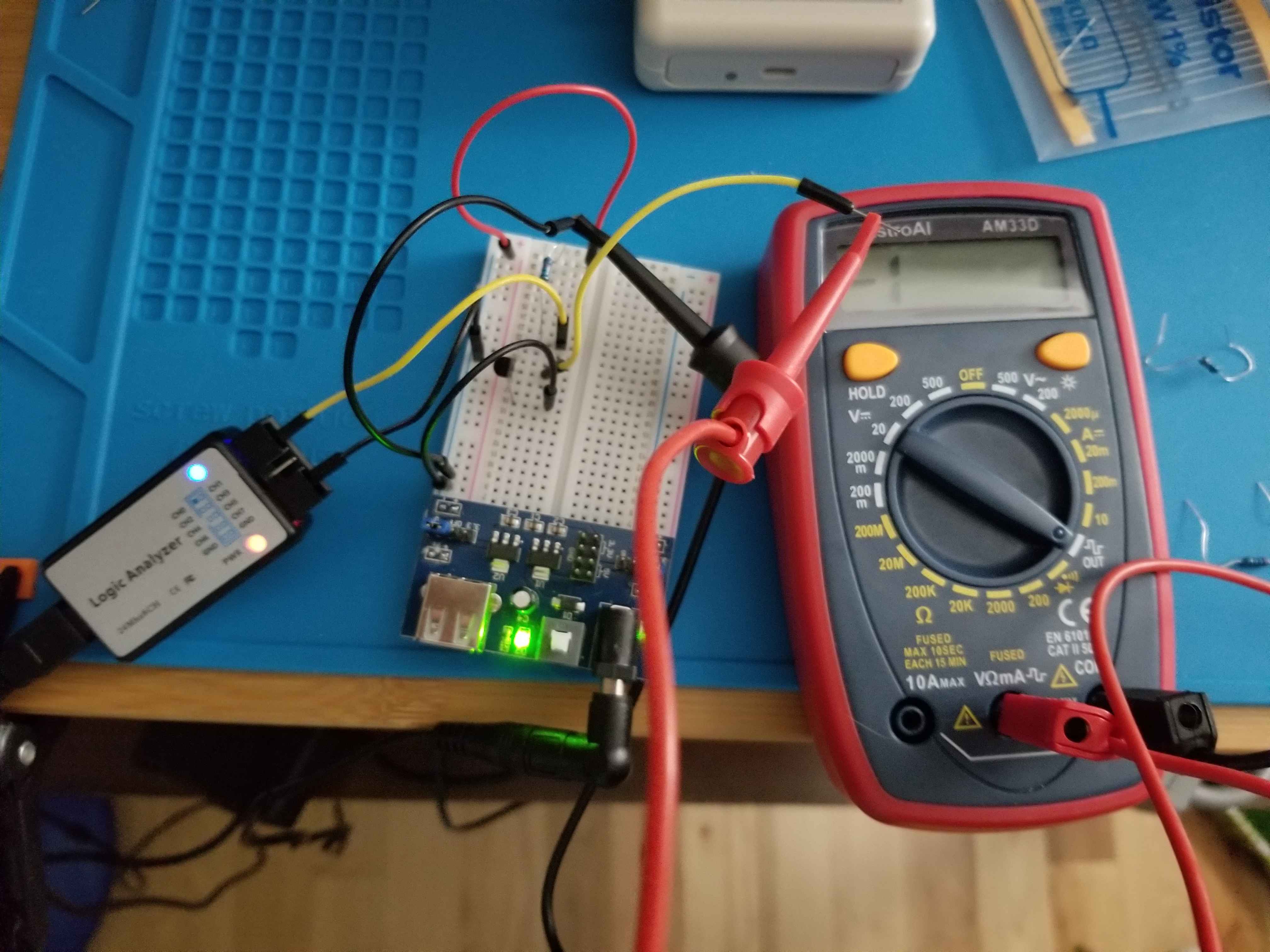
I finally found a different way to measure the frequency of the test signal: I put together a transistor switch circuit to convert the mulimeter test signal into logic pulses, and then used a logic analyzer to count the pulses. The setup is similar to the one I used in Measuring Fan Speed With a Logic Analyzer.
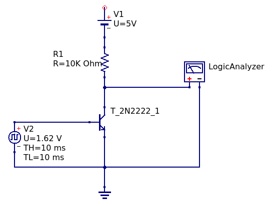
I used an NPN 2N2222 transistor. I connected the collector to a 10K Ohm resistor connected to a 5V DC source (I determined these after some trial and error and reading forums), the emitter to GND, and the base to the multimeter test signal. The test signal ranges from +1.62V to -1.37V. It flipped the voltage at the collector between 0V and 5V. I connected the logic analyzer input to the transistor collector.
Here is a diagram of the circuit:
Here is a picture of the setup:
Finally, here is a screenshot of the measurement in PulseView:
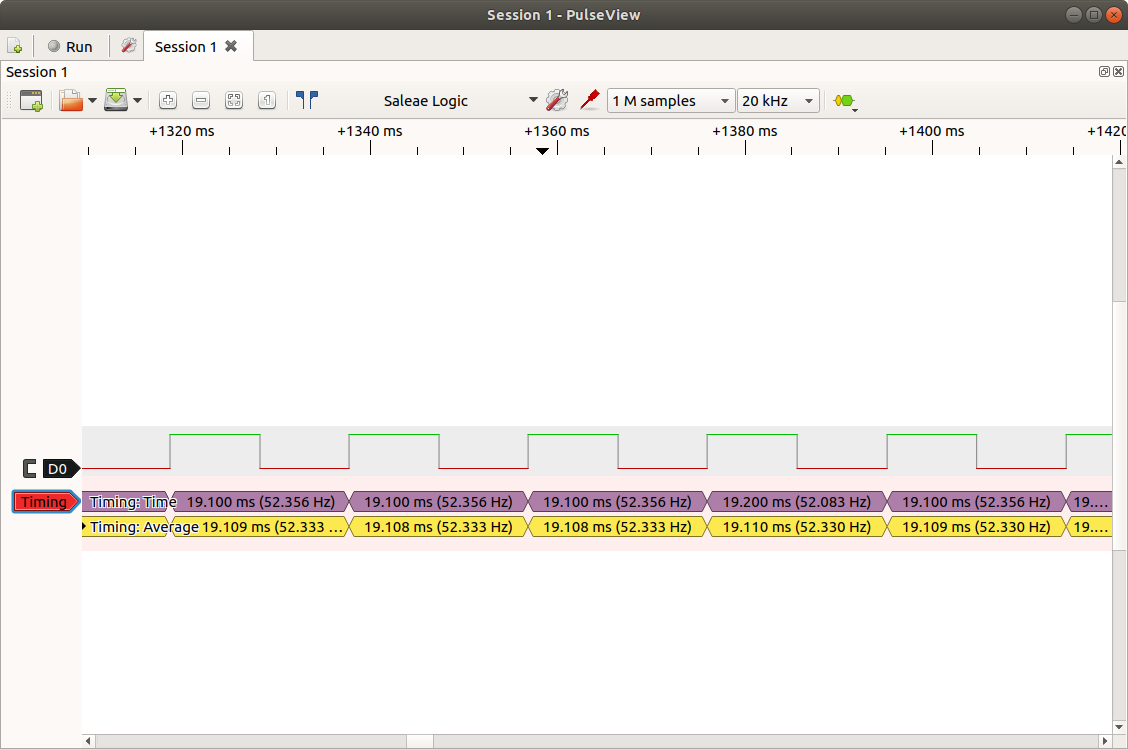
The logic analyzer measured the test signal frequency at 52.3 Hz. This confirms the oscilloscope measurement and shows the multimeter is a bit off from spec. (The multimeter documentation uses the word “approximately” for voltage range of the test signal…maybe “approximately” applies to other parameters too.)
This project was a great follow up to Measuring Fan Speed With a Logic Analyzer and a great way to start learning about transistors. It was also very satisfying to finally confirm the oscilloscope measurement of the multimeter test signal.
subscribe via RSS